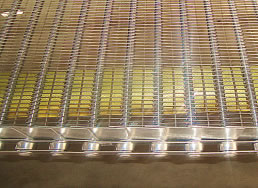
Eye Link Conveyor Belt
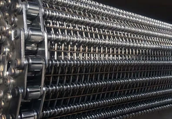
Designed for harsh applications that require an extremely heavy-duty belt, Eye link belts are custom designed with almost unlimited configurations to meet your applications demanding requirements. Additionally, Eye link belts are available with multiple drive options including friction driven cage rollers, positive drive sprockets, and an optional chain edge drive for enhanced tracking and reliability.
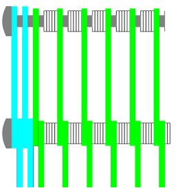
Specification
Belt specification details
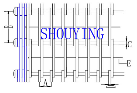
| A | Loop wire pitch |
| B | Cross rod pitch |
| C | Cross rod diameter |
| D | Loop wire diameter |
| E | Diameter and number of underwires |
General size
| Dimension | Production capabilities | |||||
| A=Cross rod pitch (mm) | 30.0 - 75.0 | 30.0 | 50.0 | 50.0 | 75.0 | 50.8 |
| B= Loop wire pitch (mm) | 4.0 - 25.0 | 4.0 | 7.5 | 12.5 | 15.0 | 11.0 |
| C=Loop wire diameter (mm) | 2.0 - 3.0 | 2.0 | 2.5 | 2.5 | 2.5 | 3.0 |
| D=Cross rod diameter (mm) | 4.0 - 8.0 | 4.0 | 5.0 | 5.0 | 8.0 | 8.0 |
| E=Diameter and number of under welded wires (mm) | 1.5, 2.0, 2.5 and 3 mm, number of underwires: 0, 1 and 2 | to be confirmed |
to be confirmed |
to be confirmed |
to be confirmed |
to be confirmed |
| Plate links width (mm) | max 3.5 | with plate links | with plate links | with plate links | with plate links | with plate links |
Eye link belt types
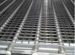
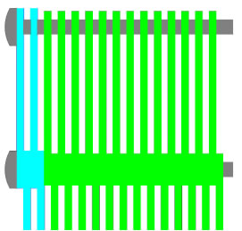 |
Eye-link belt without spacers |
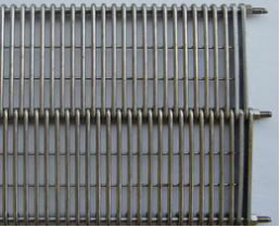
 |
Eye-link belt with under welded wire spacing |
 |
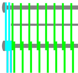
Eye-link belt with rings as spacers |
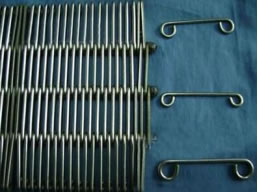
 |
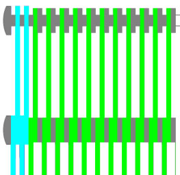
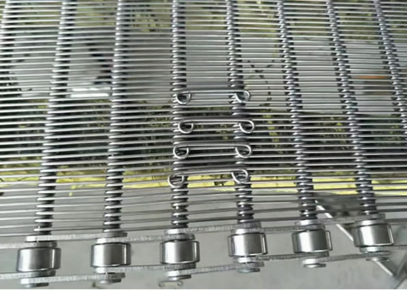
Eye-link belt with springs as spacers |
Belt edges
 |
Standard plate edge |
 |
Reinforcing plate edge |
 |
Chain link edge |
 |
Side guard edge |
Materials available
Stainless steel 304
Stainless steel 316
Galvanized steel
Carbon steel
Other materials demanded by the clients.
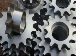
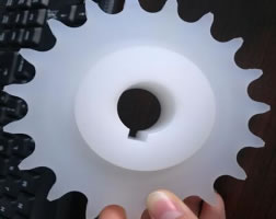
Sprocket
In order to choose the most appropriate sprocket material for you application, please considering the conditions under which the belt will operate. Conditions such as temperature variations, erosion, abrasion.
Sprocket material include
Stainless steel, Nylon, Delrin.
 |
 |